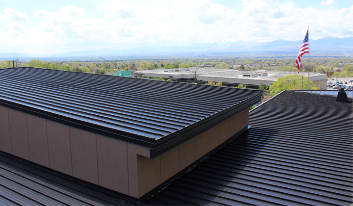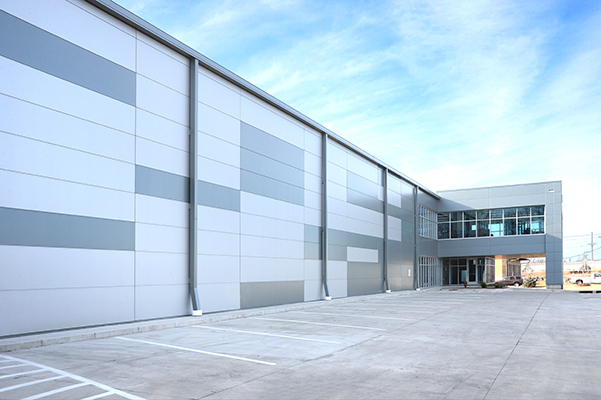
Metal roofing and wall panels routinely come from the factory pre-finished a durable, baked-on paint finish that covers the Galvalume®-coated steel surface. This production occurs in a controlled environment, which helps create a consistent product, and allows metal panels to last decades with minimal maintenance. It turns out, however, that the biggest threat to a metal panel’s paint coating can happen during panel installation. Tools, fasteners and other installation-related items and activities can scratch or damage the finish, requiring touch-ups to the paint. If you experience this, here are some touch-up paint tips to keep in mind.
Assess the Damage
First, determine how noticeable the scratch is. Do you have to be close to see it, or can you see it easily from several feet away? Generally, if the scratch isn’t noticeable and has not penetrated the Galvalume coating, its best to refrain from doing a paint touch-up. This is because touch-up paint can’t match the fade resistance of the original baked-on pre-finish, and if the Galvalume is still intact, it will still protect the steel beneath the scratch.
On dark or bright colors in particular, the touch-up paint will fade much more quickly than the original paint. Often, the end result is that touch-up paint is more noticeable than if the scratch is left alone. On the other hand, if the scratch is noticeable and needs a touch-up, there are some best practices to follow. It’s important to note though, that if a large area of the panel is damaged (more than 10–15%), then it’s best to just replace the panel.
Getting the right touch-up paint
Metal panel manufacturers recognize that there may be a need for minor paint touch-ups in the field. So, most offer small containers of paint conducive to field work. These paints are specifically formulated to match standard color offerings, and have properties that make them compatible with the factory finish. Therefore, it’s important to always buy touch-up paint from the manufacturer that produced the original panels. Never ask a paint store to match colors based on a piece of panel or trim. Doing so may get a color match, but it won’t contain the other protective properties of the paint coating you receive from a manufacturer.
Choice of touch-up paint application
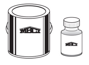
Touch-up paint for field application is often available in three types of containers: paint pens, small bottles and spray cans. Usually, the best choice for a scratch is a paint pen. Touch-up paint pens have small, precise tips that can fit into scratches, allowing it to only apply paint where needed. For larger scratches or scuffs, manufacturers offer bottles of paint (with a small brush) similar to those used for nail polish. Generally, these are best for dings on the panel.
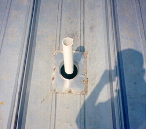
Spray cans are also available, and are ideal for painting small accessories like plumbing vent pipes. Don’t use spray cans to conceal a scratch because they apply much more paint than necessary. This can cause unsatisfactory results as the paint weathers and fades differently than the original paint.
Using touch-up paint
When performing a paint touch-up, it’s important to make sure the area in and around the scratch is clean and dry. Wipe down the area as needed, then dry it completely before applying any paint. Afterward, paint the surface using the least amount of paint necessary. This eliminates excess paint on the pre-finished panel. Paint pens are ideal for this since they apply less paint than a nail polish-type bottle or spray can. Once the touch-up paint is on the panel, it will need time to dry. During drying, make sure that dust or other contaminants do not embed into the wet paint.
Consult the metal panel manufacturer
To ensure you or your maintenance professional properly select and apply touch-up paint, be sure to check all warranty and installation requirements and resources with the metal panel manufacturer. They can help ensure you get touch-up paint that matches the paint originally used on your panels and that you take the right steps to ensure warranties remain intact. MBCI offers metal panel touch-up paint for industries and applications including:
- Agricultural
- Architectural
- Commercial and Industrial
- Insulated Metal Panels
- Residential
- Standing-Seam Metal Roofing
For more on metal roof and wall panel finishes, colors and touch-up paint techniques, contact your local MBCI representative.